Solar Panel Grounding and Earthing: Complete DIY Guide
Do solar panels need to be grounded?
Yes. Every electrical code that covers photovoltaics — NEC 690 in North America, IEC 60364-7-712 and its national versions like VDE 0100-712 in Europe — requires the exposed metal of a solar array to be connected to earth. Grounding does two separate jobs: bonding ties every metal frame and rail together so no part can sit at a different voltage than the rest, and earthing connects that bonded metalwork to an earth electrode so a fault or a nearby lightning strike has a safe path into the ground instead of through a person.
A solar array is a special case among electrical installations: it sits outdoors for 25+ years, it cannot be switched off while the sun shines, and its DC side can run at 400–1000 V. An insulation fault that would trip a breaker in ordinary house wiring can leave a panel frame silently energized for months. That is why bonding is mandatory even for small DIY systems, and why the array's earth must be the same earth as the rest of the building.
Grounding is not optional on 'small' systems
Grounding, bonding, earthing — three words, one system
The words grounding, earthing and bonding get mixed up constantly, and the confusion causes real installation errors. They describe different connections with different purposes:
| Term | What it connects | What it protects against |
|---|---|---|
| Bonding (equipotential) | Panel frames, rails, mounting hardware — all metal to all metal | Voltage differences between parts you can touch at the same time |
| Protective earthing | The bonded metalwork to the building's earth electrode | Electric shock from insulation faults; lets protection devices trip |
| Functional earthing | One DC pole to earth — only in special systems, via the inverter | Degradation effects (PID) in specific module technologies |
| Lightning protection (LPS) | Air terminals and down conductors to dedicated earth electrodes | Direct lightning strikes — a separate system under IEC 62305 |
For a typical DIY grid-tied system, your job is the first two rows: bond everything, then earth the bonded whole. Functional earthing of a DC pole is the inverter manufacturer's decision, never yours — more on that below. A full lightning protection system with air terminals is a separate engineered installation that most homes do not have.
Why panel frames become live
A solar panel's aluminum frame is separated from the cells by the laminate and the anodized oxide layer on the metal itself. Three things defeat that separation over the years. First, insulation faults: a cracked backsheet, a chafed cable pinched under a clamp, or moisture creeping into a junction box can connect a live conductor to the frame directly. From that moment the whole rack is at string potential — up to several hundred volts — waiting for someone to touch it and a path to ground.
Second, capacitive leakage. A panel is a large conductive sheet (the cells) facing another large conductive sheet (the frame and the grounded roof) — a capacitor. On transformerless inverters, which have no galvanic isolation between DC and AC, the DC side is not fixed at a constant potential relative to earth; parts of the array swing with the grid voltage. This drives a small but permanent AC leakage current through that capacitance, typically a few milliamps for a residential array. Bonding gives this current a designed path; without it, the path is whatever touches the rack.
Third, potential-induced degradation (PID). When cells sit at a large negative voltage relative to the grounded frame, sodium ions migrate from the glass into the cell and output can drop 10–30% over a few years. Proper frame grounding does not cause PID — it defines the reference against which the module was tested and certified. Some inverters counter PID with built-in functional earthing or nighttime recovery circuits.
The frame is insulated from the cells — so why bond it?
Bonding the array step by step
Bonding sounds trivial — 'connect the metal together' — but aluminum makes it subtle. Every structural part of an array is anodized or coated, and anodized aluminum oxide is an excellent insulator. Two rails touching each other are not necessarily bonded. A proper bond must pierce the coating and stay gas-tight for decades:
- Bond each panel frame to the rail
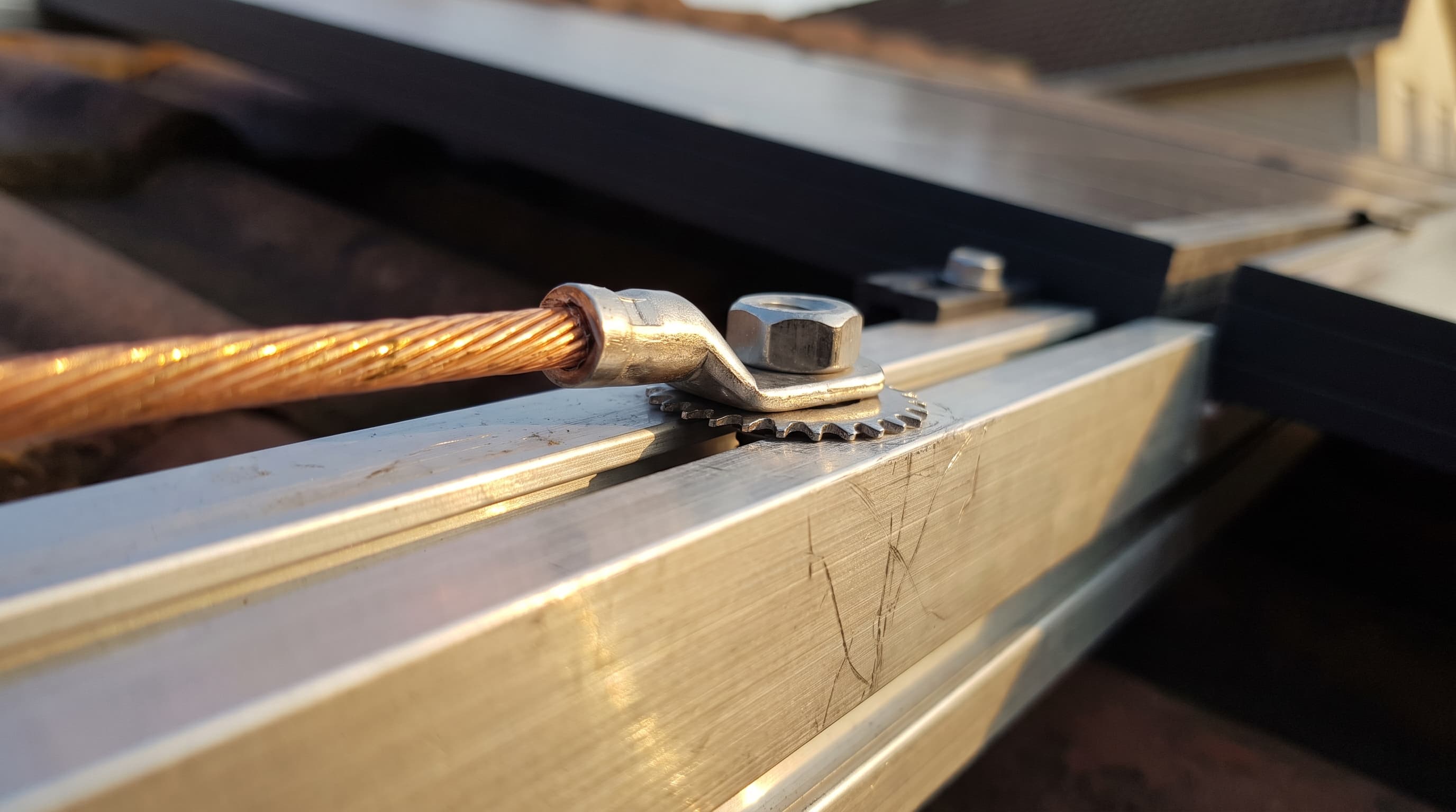
Use hardware listed for bonding — serrated grounding washers (WEEB type), bonding mid-clamps with piercing points, or the grounding hole marked ⏚ on the frame with a listed lug. The serrations bite through the anodizing into bare metal.
- Bond the rails to each other
Rail splices are mechanical joints, not electrical ones, unless the splice kit is listed for bonding (in North America: UL 2703). Otherwise add a bonding jumper across each splice.
- Connect the earthing conductor to the rack
One listed lug per rail row (or per the racking manual), copper conductor, stainless hardware. Copper must never touch aluminum directly — the lug body isolates the two metals to prevent galvanic corrosion.
- Run the conductor to the earthing point
Route the earthing conductor together with the DC cables — close, without loops. Continuous run wherever possible; where a splice is unavoidable, use an irreversible (crimped) or listed connection, never a wire nut.
Rail as grounding path: only if listed
Earthing conductor sizing
The cross-section of the earthing conductor depends on one question: is there an external lightning protection system (LPS) on the building, and if yes — does the array keep the required separation distance from it? These are the minimum copper cross-sections used in European practice (VDE 0100-712 with the IEC 62305 lightning series) and the NEC equivalent:
| Scenario | Min. copper size | Note |
|---|---|---|
| No external LPS on the building | 6 mm² | Equipotential bonding of the rack to the main earthing terminal |
| LPS present, separation distance kept | 6 mm² | Array stays outside the LPS; bond to the main earthing terminal only |
| LPS present, separation distance NOT kept | 16 mm² | Rack must be bonded to the LPS with lightning-current-rated connectors |
| NEC (North America) | 10 AWG / 8 AWG | Sized per NEC 250.122 from the circuit's overcurrent device; 6 AWG bare where exposed |
Bigger is never wrong: many installers simply run 16 mm² (or 6 AWG) everywhere so the question of separation distance can never bite them later. The cost difference on a residential array is a few euros.
Route it with the DC cables, without loops
Lightning protection and separation distance
Bonding and earthing protect against faults and induced surges — they do not make an array lightning-proof. Direct strike protection is a separate system under IEC 62305: air terminals, down conductors and their own electrodes. If your building has one, the key concept is the separation distance: the minimum air gap (typically 0.5–1 m, calculated per IEC 62305-3) between the LPS and the array's metalwork that prevents a strike from arcing over into your DC wiring.
If the array can keep that distance from every down conductor and air terminal, it stays electrically independent — earth it with 6 mm² to the main earthing terminal and you are done. If it cannot (common on small roofs), the rack must be deliberately bonded into the LPS with lightning-rated clamps and 16 mm² copper, so strike current has a controlled path around your equipment rather than through it.
Whether or not an LPS exists, surge protective devices (SPDs) on the DC side are the second half of lightning safety: they clamp the voltage spikes that nearby strikes induce in the string wiring. An SPD is only as good as its earth connection — a type 2 DC SPD with a long, thin, looping earth wire clamps at a far higher let-through voltage than its datasheet promises.
Grounding ≠ lightning rod
Transformerless inverters: never earth DC+ or DC−
Here is where DIY intuition from car electrics or old telecom systems causes real damage: on a modern transformerless string inverter, neither DC pole may be connected to earth. The array must float. Practically every current residential string and hybrid inverter is transformerless — there is no isolation transformer between your panels and the grid, so a DC pole tied to earth would drive fault current through the inverter's bridge on the first switching cycle.
Floating does not mean unprotected — it is the protection. The inverter measures the insulation resistance of the whole array against earth every morning before it connects (the Riso test) and monitors residual current while running. A first insulation fault on a floating array causes no fault current at all: the inverter reports an insulation error and refuses to start, and you fix the fault before it can hurt anyone. On an earthed-pole system, that same first fault is already a short circuit.
Functional earthing of a pole does exist — some thin-film and high-efficiency n-type module technologies historically required a grounded negative or positive pole to prevent degradation. But that earthing happens inside the inverter through a controlled, fused path, enabled in the inverter's settings per the module manufacturer's instruction. It is never a wire you add yourself.
Frame to earth: yes. DC conductor to earth: never yourself
The earth electrode
All bonding ends at an electrode in actual soil. For a rooftop array on a house, that is the building's existing earthing system — a foundation earth electrode or existing rods at the main earthing terminal. You do not need a new electrode; you need a proper connection to the one that is there. The resistance of a single vertical rod can be estimated from the soil resistivity:
Earth resistance of a vertical rod
R ≈ ρ / (2 × π × L) × ln(4 × L / d)With typical soil at ρ = 100 Ω·m, a 2.4 m rod of 16 mm diameter gives roughly 40 Ω. That single number explains most earthing practice: one rod is rarely enough in poor soil, doubling rod length does not halve resistance (the logarithm sees to that), and two rods spaced at least their own length apart work far better than two rods side by side. Common practice targets 10 Ω or better for systems with lightning exposure; NEC 250.53 accepts a single rod only if it measures 25 Ω or less, otherwise a second rod is mandatory.
Ground-mounted arrays deserve special care: the array gets its own local electrode (often the driven pile foundations themselves), but that electrode must still be bonded back to the house earthing system via the cable trench. An isolated array earth is a classic error — during a nearby strike, 'array earth' and 'house earth' can differ by tens of kilovolts, and the DC cable insulation between them takes the difference.
7 common grounding mistakes
- Lug on anodized or painted metal
A lug bolted onto intact anodizing makes a connection that measures fine today and is an insulator after five years of oxide growth. Use serrated hardware that pierces the coating, or clean to bare metal and protect the joint.
- Copper directly on aluminum
Copper against aluminum in outdoor humidity is a galvanic cell — the aluminum corrodes away under the connection. Always use listed bimetallic lugs or stainless interfaces between the copper conductor and the aluminum rack.
- Daisy-chaining frames with one thin wire
Looping a single 4 mm² wire from frame to frame in series means one loose screw unbonds everything after it. Bond each row to the rail system and size the conductor per the table above.
- An isolated ground rod for the array
A separate rod that is not bonded to the building's earthing system does not add safety — it creates a potential difference between two 'earths' that appears across your equipment during every nearby strike. One earthing system, everything bonded together.
- Earthing a DC pole 'for safety'
On a transformerless inverter this causes fault current, a damaged inverter, or a disabled insulation monitor. The array floats; only frames and rails are earthed.
- Treating the rail splice as a bond
Rail connectors join rails mechanically. Unless the splice is explicitly listed for bonding, strike current and fault current see an anodized joint — add a jumper.
- Forgetting the SPD's earth path
A surge protector with 1.5 m of coiled 4 mm² wire to the earth bar clamps thousands of volts higher than specified. SPD earth leads: short, straight, and at least the SPD manufacturer's minimum cross-section.
Standards overview and tools
The rules in this article come from a small set of standards. You rarely need to read them cover to cover, but knowing which document owns which question helps when your local inspector, your racking manual and a forum thread disagree:
| Topic | North America (NEC) | Europe / international (IEC) |
|---|---|---|
| Bonding of frames and racks | NEC 690.43; hardware listed to UL 2703 | IEC 60364-7-712 / VDE 0100-712; racking manufacturer certificates |
| Earthing conductor size | NEC 250.122 (typically 10–8 AWG; 6 AWG bare exposed) | 6 mm² Cu; 16 mm² Cu when bonded to an LPS |
| Earth electrode | NEC 250.52–53; 25 Ω rule for single rods | National wiring rules; ~10 Ω practice with lightning exposure |
| Lightning protection | NFPA 780 | IEC 62305 parts 1–4 (separation distance in part 3) |
| DC pole earthing | NEC 690.41 — functional grounding via the inverter only | Inverter-internal per manufacturer; floating array is the norm |
Grounding keeps the array safe to touch; the electrical design keeps it safe to run. Before anything goes on the roof, verify that your string voltage and current actually fit your inverter at your site's temperature extremes — that is a two-minute check:
Check your string in the compatibility calculator
Cold-weather Voc, MPPT window, current limits — 11 checks against real datasheet specs of your exact panel and inverter.
Size your DC cables and voltage drop
Pick conductor cross-section by voltage drop and ampacity at real operating temperature — for the same trench your earthing conductor runs in.
Fuses and breakers for solar systems
The other half of electrical safety: when strings need fuses, how to size the AC breaker, and what breaking capacity means.
Frequently asked questions
Do solar panels need to be grounded?
Yes — every electrical code requires it. Panel frames and mounting racks must be bonded together and connected to the building's earthing system. This protects against shock from insulation faults and gives surges induced by lightning a safe path to ground.
What size wire do I need to ground solar panels?
In European practice: 6 mm² copper, or 16 mm² if the rack is bonded to an external lightning protection system. Under the NEC, the equipment grounding conductor is sized from the overcurrent device per 250.122 — typically 10 or 8 AWG, with 6 AWG bare copper where it runs exposed.
Can the mounting rails be used as the grounding path?
Only if the racking system is certified for bonding (UL 2703 in North America, a manufacturer's bonding certificate in Europe) and installed exactly per its manual, including listed bonding clamps and splices. Otherwise, each frame needs its own listed lug or bonding washer.
Does grounding protect my panels from lightning?
Partially. Bonding and earthing protect against induced surges from nearby strikes — especially together with DC surge protective devices. Only a dedicated lightning protection system with air terminals protects against a direct strike.
Should I ground the negative DC wire?
No. Modern transformerless inverters require a floating array — earthing either DC pole causes fault current and can destroy the inverter. Where a module technology genuinely needs pole earthing, the inverter provides it internally through a controlled, fused path.
How deep does a ground rod need to be?
A standard rod is 2.4 m (8 ft) and must be in full contact with soil over its length. If a single rod measures above the required resistance (NEC: 25 Ω), add a second rod spaced at least one rod-length away and bond them together.
Do off-grid systems need grounding too?
Yes — bonding of frames and racks is identical off-grid. Whether one conductor of the battery/DC system is earthed depends on the inverter and charge controller design; follow their manuals. The array-side rule is unchanged: frames earthed, DC conductors floating unless the equipment earths them internally.
Can I connect the solar ground to my house earth?
You must — that is the correct design. All earthing in one building belongs to one system, joined at the main earthing terminal. Separate, unbonded electrodes create dangerous potential differences during faults and lightning events.


Discussion
Sign in to join the discussion
We require a quick sign-in to keep this thread free of spam.
No comments yet. Be the first to share your experience.